A Network Checklist for Architects at First Fix
What to settle before the walls close
Published November 2026 · Custom Controls · Home network and smart home specialists since 1998
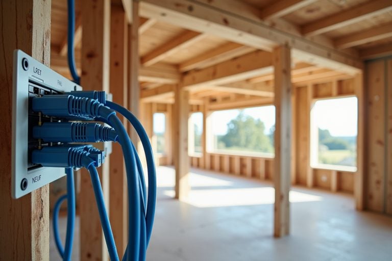
The network is the one system in a large house that cannot be added later without cutting into finished walls, ceilings and floors. Lighting, audio and video can be revised after completion, and equipment can be swapped as it ages, but the cable routes, the equipment rooms and the positions of access points are fixed at first fix and the house lives with them for decades. A good decision made at the right moment costs almost nothing. The same decision made after plastering means opening up finished work.
Architects and designers are, understandably, not expected to be network engineers, and the information needed at first fix is quite specific: how big the equipment room must be, where it should sit, how cables reach it, which positions need cabling, what the internet provider needs and how outbuildings will be linked. This checklist collects those decisions in the order a project meets them, with the reasoning behind each so that it can be adapted to the building in front of you.
It is written for architects, interior designers and main contractors working on new builds and major renovations of large houses and estates, and it supports our network design for new builds and renovations service, which produces the network section of the specification: equipment room layouts, cable schedule, access point plans, containment and electrical requirements.
1. The Equipment Room
Every network has a heart: the room or cabinet where the internet connection arrives, the switches, the firewall and the supporting equipment live. In a large house it is a proper room, not a cupboard, and its position and specification are the first decision. It should be central enough to keep cable runs within the 100-metre limit for copper Ethernet to every point it serves, accessible to engineers without going through bedrooms, and away from water pipes, wet areas and anywhere that could flood. It should also be somewhere that heat can be managed, because switching and power equipment generates a continuous load.
Size is the most common thing to get wrong. Equipment rooms are drawn to fit the equipment that is current when the drawings are made, and the equipment then grows. Allow for the racks needed now, space for expansion, a battery backup unit, cable management and room for an engineer to work at the front and back of the rack. Secondary cabinets on each floor, or in each separate building, often make sense in a large house, and their positions need agreeing on the drawings in the same way.
- Position: central, accessible, away from water and not behind a locked door that only one person can open.
- Size: space for current racks, growth, battery backup and working access to the front and rear.
- Ventilation or cooling: continuous heat load, with a plan for removing it, whether by air movement or cooling.
- Power: dedicated circuits with spare capacity, positioned for the racks and for backup equipment.
- Access: a door, a floor loading and a route that suit equipment being delivered and replaced.
2. Containment, Risers and Routes
Cables need paths, and the paths need to be on the drawings. Risers between floors, containment along corridors, routes across ceiling voids and sleeves through structural elements should be coordinated with the structural engineer, the electrician and the services designer, because network cable must be kept apart from mains power and should not be left to find its own way. It is much easier to agree a clear route with other trades than to discover that the best route has been taken by ductwork.
The aim is containment that can be added to. A route sized exactly for the cables installed today leaves no room for tomorrow, so we plan spare capacity in risers and containment. Fire stopping where cables pass through compartment walls and floors, and the integrity of acoustic and thermal constructions, need to be maintained, and the detail of how this is done belongs in the specification, not the site conversation.
Existing buildings add a further step. In a renovation, the best route for new cable is often one that already exists, such as an old bell wire route, a redundant conduit or a lighting riser, and surveying what is in the building early can avoid opening finished work. Where new cable must go through finished surfaces, joinery and ceiling openings that are being modified anyway give the best chances.
 Network Design for New BuildsCabling, comms rooms and access point positions planned before the walls close.
 For Architects and DesignersHow we work with design teams from concept to handover.
 Managed Home NetworkMonitoring and support once the house is occupied.
 Home Network and WifiThe full range of wifi and network services.
 Home AutomationLighting, heating, music, video, security and blinds under one system.
3. Cabling Specification
Category 6A copper carries 10 gigabit Ethernet over typical in-building runs, and fibre carries far more. Access points, switches and wireless standards are replaced every few years, but the cable in the walls is not, and today’s access points already arrive with multi-gigabit connections that make full use of it. Installing the right cable at first fix is the difference between a network that can be upgraded by changing equipment and one that has to be rebuilt.
Generic cabling for homes is covered by standards: ISO/IEC 11801-4 and the European equivalent BS EN 50173-4 for the cabling design, and EN 50174 for installation. They set out the structure and the performance classes, and a specification that names them gives the installer and the client a recognised baseline. We specify the cable type, containment and termination points together, with more than one cable to each access point position, spare capacity to each room for devices not yet chosen, and labelled, tested terminations.
- Category 6A to every outlet and access point position, certified on completion.
- More than one cable to each access point or key position, and spare capacity to each room.
- Fibre for backbone links between equipment rooms and to other buildings.
- Labelling at both ends of every cable, recorded on the as-built drawings.
4. Access Point and Device Positions
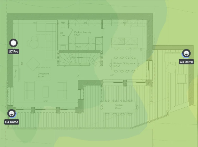
Wireless coverage is determined at first fix because that is when the cable goes in. Access points work best mounted centrally in the area they serve, usually on ceilings, with a clear path to the devices around them. A position inside a cupboard, behind a metal fitting or at the end of a corridor weakens coverage and cannot be fixed later without recabling. Stone, concrete and steel absorb and reflect signal in different ways, which is why a survey of the building’s construction should inform the positions.
Access points are one of many devices that need a cable and a position. Cameras, door stations, touch panels, keypads, wall-mounted displays, intercoms and sensors all sit on the network, and each needs a data point, often with power over Ethernet. The interior designer’s drawings are where these positions are settled, because a ceiling access point and a wall-mounted touch panel both have to look intentional. Raising them early lets the designer finish the positions properly instead of discovering them on site.
Outdoor coverage is its own question. Terraces, pool areas, gardens and approaches need outdoor access points or cameras with their own cabling, and the routes for those cables have to be agreed before landscaping, as they are for any outbuilding link.
5. Power over Ethernet
Power over Ethernet lets a single data cable carry power to the device, which is why access points, cameras, door stations and touch panels can be placed where they are needed without a nearby socket. The standard has grown over time. IEEE 802.3bt defines Type 3 delivering up to 60 watts at the switch port and Type 4 delivering up to 90 watts, using all four pairs in the cable, and these higher powers are used by devices such as multi-radio access points and pan-tilt cameras.
Power in a cable produces heat, and in a large bundle of cables the heat builds up. The TIA TSB-184-A guidance on powering over balanced twisted-pair cabling limits the temperature rise in a bundle, and recommends Category 6A for new installations carrying 4-pair PoE, which is one more reason to specify it. For the architect, the practical consequences are modest: avoid very large bundles in confined spaces, and leave enough containment space that bundles can be arranged properly and spread out.
PoE also moves the power question to the equipment room. Switches that supply PoE draw substantial power and should be on the backup supply, which is a good reason to put battery backup in the specification from the start.

6. Internet Entry and Resilience
The internet connection has to get into the building, and the route needs a duct. Provider fibre normally arrives in the ground, and the position of its entry point, the duct from the boundary to the equipment room and any chambers along the way should be on the drawings and agreed with the provider. A second connection, whether another fibre route, a mobile connection or satellite, needs its own route and its own position, so that the two do not share a failure.
4G, 5G and satellite connections also need aerial positions. A mobile antenna works best with an unobstructed position high on the building, and a satellite dish needs a clear view of the sky, both with cable routes to the equipment room. These are easy to include in a design and difficult to add to a finished roof, particularly where the roof finish is slate, lead or thatch. Our guide to failover design for chalets explains how the connections work together.
7. Outbuildings, Gatehouses and Grounds
Detached buildings are linked to the main network by fibre in duct wherever a route can be laid, or by point-to-point wireless where it cannot. The duct route is part of the landscape design, and it should be drawn before the drive, the planting and the drainage are fixed, with chambers at changes of direction and spare ducts for later use. Each building also needs its own cabinet, its own power for the network equipment and its own cabling to a standard that matches the house. Our guide to fibre versus wireless between buildings sets out how to choose.
Grounds bring their own requirements: cameras at gates and perimeters, outdoor access points near pool terraces, gate controllers and lighting control. These all need cable and often power, and the routes are generally in the same trenches as the services. Co-ordinating them early avoids digging up new landscaping.
8. Coordination With Other Trades
The network touches almost every other system. The electrician supplies the circuits for the equipment room and the sockets for backup power. The audio and video design needs data points at screens, speakers and equipment locations. Security and access control need cable to every camera, door station and gate. Lighting control and heating need connections to controllers. If the network is designed first, with the architect, the interior designer and the contractor, the infrastructure serves them all and nothing is retrofitted.
Responsibilities should be written down. The specification should say who supplies and installs the cable, who terminates and tests it, who is responsible for containment, and who is responsible for fire stopping and making good. Ambiguity at this stage causes trouble on site, where the cabling contractor assumes the electrician has installed containment that the electrician assumed was in someone else’s scope.
9. Testing, Records and Handover
Every cable should be labelled and tested, and the results recorded, before the walls are closed. A certification test of each link measures the cable’s performance against the standard and documents it, and the records show later whether a fault is in the cabling or the equipment. Photographs of concealed routes before plastering, marked on the plans, are extraordinarily useful to whoever opens the wall in ten years’ time.
The as-built information is part of the handover: drawings showing where every cable and cabinet is, the cable schedule, the test results, and the equipment and addressing records that follow when the active equipment is commissioned. Our post on what a network handover pack should contain sets out the full list.
The First-Fix Checklist in One Place
For use on the drawing board and on site, the points above reduce to a short list of questions. If each has a clear answer on the drawings before first fix, the network will be right while it is still easy to make right, and the trades that follow, from the electrician to the interior designer, will know exactly what the infrastructure needs from them and when.
The list is deliberately short, because the real value of a first-fix review is in the conversation around it. Each question has consequences for another trade, and the quickest way to resolve them is a short meeting between the architect, the contractor and the network designer, with the current drawings on the table. The answers are then written into the specification, so that nobody has to remember them.
- Is there an equipment room of the right size and position, with power, ventilation and access, and secondary cabinets where needed?
- Are risers, containment and routes drawn, coordinated with other trades and sized with spare capacity?
- Is Category 6A specified to every outlet and access point position, with more than one cable to key locations?
- Are access point, camera, door station and touch panel positions agreed with the interior designer?
- Is the PoE load allowed for in cable bundles and in the equipment room’s backup power?
- Are internet entry ducts and aerial positions for a second connection on the drawings?
- Are outbuilding links, ducts and cabinets drawn, with fibre routes agreed before landscaping?
- Is every trade’s responsibility for cable, containment, fire stopping and testing written down?
- Will every cable be labelled, tested and photographed, with records handed over?
Frequently Asked Questions: Networks at First Fix
- What is first fix for the network?
First fix is the stage after the structure is up and before plastering, when cables are run to their positions and containment is installed. It is the last point at which cable routes and equipment rooms can be changed without cutting into finished work. - What cable should be specified for a new build?
Category 6A copper to every outlet and access point position, certified on completion, with fibre for links between equipment rooms and to other buildings. It carries 10 gigabit Ethernet over typical in-building runs and supports power over Ethernet. - How big should the equipment room be?
Large enough for the racks needed now, room for growth, battery backup, and working space at the front and rear of the rack. Equipment rooms are usually drawn too small, so allow for expansion and for secondary cabinets on each floor or building where needed. - Where should wireless access points go?
Centrally in the area they serve, usually on ceilings, with a clear path to devices. Positions are decided at first fix because that is when the cable goes in, and they should be agreed with the interior designer so the finish is intentional. - Does power over Ethernet change the cabling?
It can. Higher-power PoE under IEEE 802.3bt delivers up to 60 or 90 watts at the switch port and warms cable bundles, so Category 6A is recommended for new installations and very large bundles in confined spaces should be avoided. - Who is responsible for cabling, containment and fire stopping?
It should be written into the specification. Ambiguity between the electrician, the cabling contractor and the main contractor is a common cause of problems on site, so each trade’s scope should be stated in advance. - Can you review our drawings?
Yes. We review drawings as they develop, attend design team meetings where needed, and can provide the network section of the specification: equipment room layouts, cable schedule, access point plans, containment and duct requirements, and the electrical needs of the network.
Network Design for New Builds → · For Architects and Designers → · Managed Home Network → · Discuss your project →